Phasics
- Wavefront, MTF and QPI measurement solutions
- Products
- Applications
- Markets
- Company
- Contact us
Aug. 28, 2026
In optical manufacturing and lens assembly, engineers frequently face a frustrating scenario: every mechanical dimension measures within tolerance, lens element spacers match design values, threaded rings are torqued, and visual inspection is flawless. Yet, when placed on the testing bench, Modulation Transfer Function (MTF) testing shows a pass/fail rejection, dropping 10%–20% below design specifications at critical spatial frequencies.
While traditional MTF testing tells you that an optical system failed, it cannot tell you why. Finding the root cause using trial-and-error alignment often takes longer than building the assembly itself.
To overcome this, leading manufacturers are shifting from standalone MTF pass/fail criteria to combining MTF with wavefront measurement and Zernike aberration analysis. By inspecting wavefront errors, optical engineers can map MTF shortfalls directly to specific physical manufacturing defects, and correct them live.
1. The Physics of MTF Shortfall: Wavefront Degradation
MTF measures an optical system's ability to transfer contrast as a function of spatial frequency. At its core, MTF is a composite mathematical expression of wavefront aberration. Any optical performance loss during lens assembly is fundamentally an increase in wavefront error (WFE).
During lens assembly manufacturing, wavefront errors stem from three key areas:
2. Linking Zernike Aberrations to Real-World Production Defects
When MTF testing fails, breaking down the wavefront into Zernike polynomial aberrations allows you to pinpoint the exact manufacturing fault:
|
Zernike Aberration Signature |
Physical Production / Alignment Issue |
Impact on Optical Performance |
|
Coma |
Element Decenter & Asymmetry: Barrel bore coaxiality errors, lens element centering errors, or uneven retaining-ring torque. |
Asymmetric MTF between meridional and sagittal directions; severe off-axis degradation. |
|
Astigmatism |
Element Tilt & Mechanical Wedge: Non-perpendicular lens seats, unparallel spacer rings, or mechanical wedge. |
Separation between meridional and sagittal MTF curves; elliptical Point Spread Function (PSF). |
|
Spherical Aberration |
Axial Spacing & Form Errors: Incorrect spacer thickness, stacked spacer tolerances, or wrong radius of curvature. |
Uniform MTF drop across the entire field; aberration balance destruction between groups. |
|
High-Order / Trefoil / Trefoil-like |
Assembly Stress Deformation: Bending deformation from overtightened retaining rings or epoxy shrinkage. |
Mid-to-high spatial frequency MTF drop. |
3. Increasing Yield in Optical Manufacturing: Validating Sub-Assemblies Before Integration
A major bottleneck in optical manufacturing is validating complex sub-assemblies prior to final integration. Modern optical systems rely on multiple stacked sub-assemblies; while the fully completed lens must meet strict performance targets, individual sub-assemblies are often highly aberrated by design. Validating these inherently aberrated groups against their optical design is complex, yet essential. If a defective sub-assembly is integrated into a complete lens stack, identifying which specific optic caused an end-stage MTF failure requires costly, time-consuming disassembly.
To solve this challenge, Phasics customers implement single-pass, wavefront-based comparisons to nominal design at the sub-assembly stage. Catching manufacturing defects early drastically increases overall production yield and reduces final alignment time.
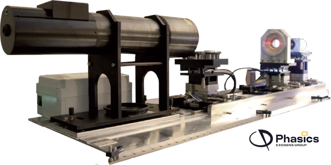
Figure 1: PHASICS test bench used for the characterization of cinema zoom-lens sub-assemblies.
While applicable to any complex optical stack, this approach is particularly critical for high-performance optics like cinema lens zoom groups, which exhibit large nominal design spherical aberration (>30 µm PV at fast apertures like F/2). Standard double-pass interferometers fail on these sub-assemblies due to ray clipping at the pupil and dynamic range constraints. Using Quadriwave Lateral Shearing Interferometry (QWLSI) via a Phasics SID4-HR wavefront sensor integrated into a single-pass test configuration, the total measured wavefront WFmeasured is expressed as:
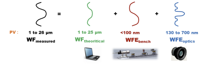
Figure 2: Decomposition of the measured wavefront into theoretical, test-bench and optical contributions.
By subtracting the theoretical design wavefront WFtheoretical and bench contributions WFbench < 100 nm PV, the setup isolates the true manufacturing residual error of the assembly under test WFoptics with sub-100 nm PV uncertainty.
Identifying Root Causes in Production Batches
Evaluating WFoptics across a manufacturing run of rear zoom sub-assemblies demonstrates the diagnostic power of tracking specific Zernike terms, such as 3rd-order spherical aberration (SA3 / Z8)—against the nominal design:
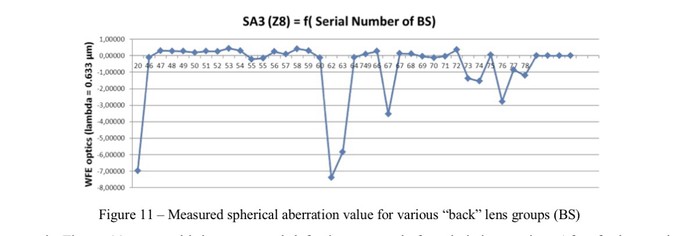
Figure 3: SA3 (Z8) Residual Aberration across Sub-Assembly Serial Numbers
By mapping the deviation in wavefront error, testing reveals the underlying physical failure mechanism rather than a simple pass/fail metric:
• Severe Deviations (e.g., SN 20, 62, 63 dropping to -4λ to -7λ): Root-cause analysis isolated the spike in spherical aberration to defective doublet bonding.
• Moderate Offsets (e.g., SN 67, 73, 74, 76 drifting to -1.5λ to -3.5λ): These departures were traced to out-of-spec air-gap spacing between singlet lenses.
By quantifying these exact manufacturing variations before final integration, manufacturers prevent non-conforming sub-assemblies from entering the final build, thereby protecting production flow, increasing final yield, and streamlining the final optical alignment process.
4. Real-Time 20 Hz Feedback: From Post-Mortem Testing to Live Alignment
Traditional MTF testing acts as an offline inspection gate: assemble the lens, mount it on a bench, measure MTF, and disassemble if it fails.
Phasics wavefront sensing technology transforms optical assembly into an active, live alignment process:
Upgrade Your Optical Alignment and Testing Process
Stop guessing why your lens assemblies are failing MTF tests. By integrating wavefront measurement and Zernike aberration diagnostics into your optical manufacturing line, you can catch sub-assembly errors early, streamline live alignment, and boost production yield.
📩 Contact our optical metrology team today to design a live wavefront and MTF diagnostic workflow for your manufacturing line!
🔔 Follow us for more on MTF, wavefront metrology, and optical alignment engineering.